
Fixing Crappy UPDI Communication
If you can’t find the mistake, maybe it’s not on you after all.
A while back, I was working on my hardware project that utilizes an ATtiny1616 from Microchip. Everything was running smoothly until the moment I tried to flash my code to it—I couldn’t get my computer to communicate to it whatsoever. It was my first time flashing a custom development board and especially with something as niche as UPDI, it scared the hell out of me. In addition to that, I only had one chip to work with. If it was broken or I happen to break it, I’d pretty much be screwed.
Luckily, I found the main problem to my communication line. I’ll also mention some other possibly relevant gotchas here. Even though I used an ATtiny1616, these tips should also work for any other microcontrollers from Microchip. But first, my setup.
Setup
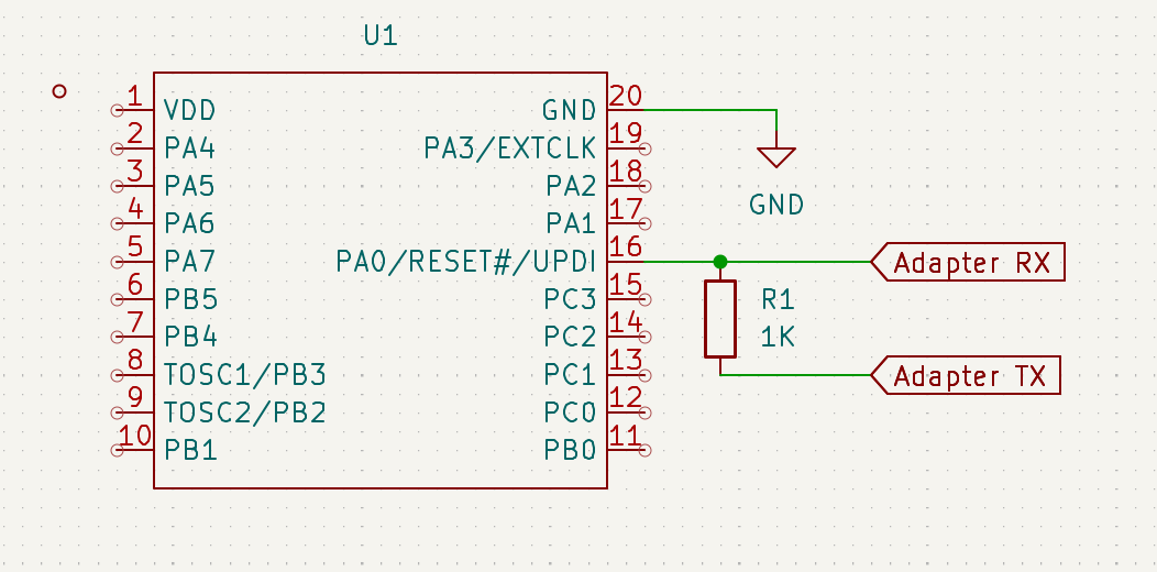
I use a CH340-based USB-to-TTL adapter, with serialupdi to flash the code. The RX of the adapter goes straight to the UPDI pin. The TX of the adapter is connected with 1KΩ of resistance to the UPDI line.
Here’s a command you can use to ping your microcontroller:
avrdude -c serialupdi -p t1616 -P /dev/ttyUSB0 -b 115200 -v -v -v
If your connection is successful, you should see lines similar to these:
AVR device initialized and ready to accept instructions
Avr_signature(serialupdi, t1616)
Reading | ####################################################### | 100% 0.02 s
Device signature = 1E 94 21 (ATtiny1616)
If the command above doesn’t work, try lowering the baud rate from 115200 to 57600, 38400, etc.
LED on RX Line
Having an LED (most likely on your serial adapter board) directly placed on the RX line may cause communication issues, so try to desolder it. As jtag2updi page puts it:
[…] The load from an LED on the UPDI line will overwhelm any signal from the target and prevent communication […]
Different Supply Voltage (NOT DIFFERENT GROUND)
The serial adapter I used was supplied a bit over 5 volts for power, while my ATtiny1616 only got around 4.9 volts. However, this is small enough that it’s negligible.
Internal Resistance
My CH340 adapter does not have internal series resistor on the TX line. There are only three resistors on the adapter, along with 3 LEDs… we can guess what those resistors are for.
Initially, I thought this would be problematic as the jtag2updi guide I mentioned above does not display any wiring with my exact setup. The closest there is on that page is this wiring with 4.2 kΩ resistor instead of my 1 kΩ:
--------------------                                   To Target device
                DTR|                                  __________________
 No resistor?   Rx |--------------,------------------| UPDI---------------->
  Are you sure? Tx |--/\/\/\/\---`          .--------| Gnd
 This is rare!  Vcc|---------------------------------| Vcc
                CTS|                     .`          |__________________
                Gnd|--------------------'
--------------------
However, 1 kΩ later worked just fine. Just stick with 1 kΩ. In my case, I can do the UPDI communication as fast as 230400 bauds.
Get a Good USB Port
The ultimate reason that I couldn’t do UPDI was because my laptop has a faulty USB controller. That’s right… it was not my crappy PCB or my cheap serial adapter. It was my laptop that costed hundreds of dollars. I’ve had this issues too before, actually. I’ve faced lots of troubles in the past in regards to flashing code, especially to Android devices running Fastboot. I have no idea of why the USB controller of my laptop sucks so much, though perhaps it’s due to my Ryzen 5600H which is known to have USB connection issues. So yeah, check your computer too. Or any other tools you use for that matter.
References
- https://michael-crum.com/attiny1616/
- https://github.com/SpenceKonde/AVR-Guidance/blob/master/UPDI/jtag2updi.md